Internal Dimple Connector
Internal Dimple Connectors are essential to make-up coiled tubing bottom hole assemblies with the greatest torsional strength while maintaining no external upset against the CT string. During installation, a dimpling yoke and jig applies thousands of pounds of hydraulic force to dimpling buttons on the external CT wall that align with the dimples on the upper section (shank) of the connector. This process creates a strong, tight fit that transmits the tensile as well as the torsional forces applied.
Design Features
- Robust one-piece design
- High torsional & tensile strength
- Ideal for jarring & milling applications
- Simple to install
- Dual elastomeric seals
- Available for all sizes of coiled tubing and wall thickness
- Customization options available
Technical Specifications
Engineered for maximum torsional transfer without external upset, each configuration uses hydraulic dimpling to lock the BHA into the CT string. Optimized for jarring and milling applications where rotational force and seal integrity can’t be compromised.
| COIL OD | WALL THICKNESS | STANDARD ID | FLOW AREA (sq inch) | O-RING | TENSILE YIELD | TORSIONAL YIELD (ft-lbs) | INTERNAL YIELD PRESSURE |
| 31.80mm (1.250″) | 2.77mm (0.109″) | 15.09mm (0.594″) | 0.277 | 210 | 11,229 daN 25,154 lbf | 694 | 68.9 MPa 10,000 PSI |
| 2.99mm (0.118″) | 14.30mm (0.563″) | 0.249 | 210 | 10,509 daN 23,542 lbf | 670 | ||
| 3.18mm (0.125″) | 12.70mm (0.500″) | 0.196 | 210 | 11,628 daN 26,048 lbf | 668 | ||
| 3.96mm (0.156″) | 11.09mm (0.437″) | 0.15 | 209 | 9,795 daN 21,941 lbf | 557 | ||
| 38.10mm (1.500″) | 2.77mm (0.109″) | 20.65mm (0.813″) | 0.519 | 214 | 17,257 daN 38,657 lbf | 1,262 | 68.9 MPa 10,000 PSI |
| 2.99mm (0.118″) | 19.81mm (0.78″) | 0.478 | 214 | 17,473 daN 39,140 lbf | 1,235 | ||
| 3.18mm (0.125″) | 19.81mm (0.78″) | 0.478 | 214 | 16,499 daN 36,959 lbf | 1,184 | ||
| 3.40mm (0.134″) | 19.05mm (0.75″) | 0.442 | 213 | 16,559 daN 37,093 lbf | 1,153 | ||
| 3.68mm (0.145″) | 16.66mm (0.656″) | 0.338 | 213 | 16,591 daN 37,166 lbf | 1,162 | ||
| 3.96mm (0.156″) | 14.30mm (0.563″) | 0.249 | 213 | 20,095 daN 45,015 lbf | 1,162 | ||
| 44.45mm (1.750″) | 2.77mm (0.109″) | 26.92mm (1.06″) | 0.882 | 218 | 23,706 daN 53,102 lbf | 1,986 | 62.05 MPa 9,000 PSI |
| 3.18mm (0.125″) | 26.19mm (1.031″) | 0.835 | 218 | 22,724 daN 50,903 lbf | 1,878 | 62.05 MPa 9,000 PSI | |
| 3.40mm (0.134″) | 26.3mm (1.035″) | 0.841 | 217 | 21,003 daN 47,047 lbf | 1,773 | 51.7 MPa 7,500 PSI | |
| 3.68mm (0.145″) | 23.88mm (0.94″) | 0.694 | 217 | 22,909 daN 51,317 lbf | 1,853 | 68.9 MPa 10,000 PSI | |
| 3.96mm (0.156″) | 23.88mm (0.94″) | 0.694 | 217 | 21,141 daN 47,358 lbf | 1,744 | 62.05 MPa 9,000 PSI | |
| 4.46mm (0.175″) | 19.05mm (0.750″) | 0.442 | 216 | 27,213 daN 60,958 lbf | 1,822 | 68.9 MPa 10,000 PSI | |
| 50.80mm (2.000″) | 3.18mm (0.125″) | 31.75mm (1.250″) | 1.227 | 222 | 30,209 daN 67,669 lbf | 2,852 | 63.4 MPa 10,000 PSI |
| 3.40mm (0.134″) | 30.18mm (1.188″) | 1.108 | 222 | 37,725 daN 73,306 lbf | 2,920 | ||
| 3.68mm (0.145″) | 30.18mm (1.188″) | 1.108 | 222 | 30,622 daN 68,595 lbf | 2,763 | ||
| 3.96mm (0.156″) | 28.58mm (1.125″) | 0.994 | 221 | 30,858 daN 69,122 lbf | 2,789 | ||
| 4.46mm (0.175″) | 26.97mm (1.062″) | 0.886 | 220 | 31,218 daN 69,930 lbf | 2,691 | ||
| 4.76mm (0.188″) | 25.40mm (1.000″) | 0.785 | 220 | 32,099 daN 71,902 lbf | 2,632 | ||
| 60.3mm (2.375″) | 3.40mm (0.134″) | 38.1mm (1.500″) | 1.767 | 225 | 48,903 daN 109,543 lbf | 5,023 | 68.9 MPa 10,000 PSI |
| 3.68mm (0.145″) | 38.1mm (1.500″) | 1.767 | 224 | 44,777 daN 100,302 lbf | 4,809 | ||
| 3.96mm (0.156″) | 36.53mm (1.438″) | 1.624 | 224 | 47,366 daN/ 106,100 lbf | 4,871 | ||
| 4.46mm (0.175″) | 36.53mm (1.438″) | 1.624 | 224 | 43,044 daN 96,420 lbf | 4,487 | ||
| 4.76mm (0.188″) | 34.9mm (1.375″) | 1.785 | 224 | 42,483 daN 95,162 lbf | 4,434 |
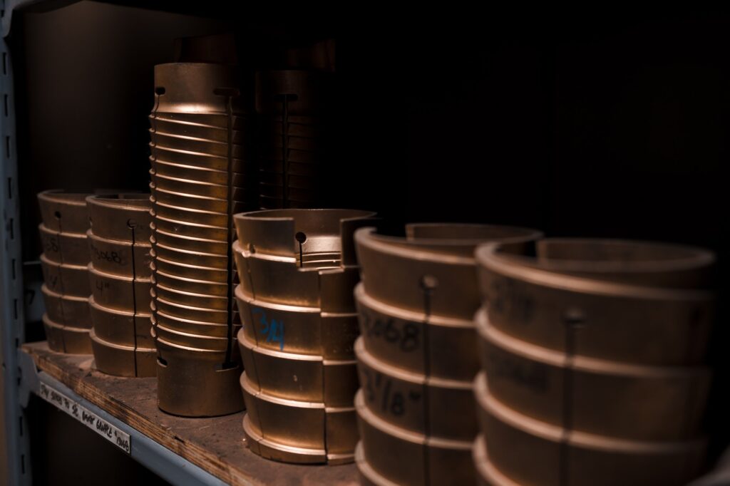
External Slip Type Connector
The Slip Connector is designed to attach the BHA to the end of the coil and transfer the axial load using slips.
The Slip Connector is comprised of a top sub, slip, brass ring, and a bottom sub with desired connection. The dressed coil is stabbed into the connector and the bottom sub is rotated to start the tightening process. An overpull is then used to set the slips further and retightening the bottom sub then ensures no further movement.
Design Features
- Torque and vibration compatible
- High torsional & tensile strength
- Versatile use for milling, drilling, fracturing
- Multiple Sizes available
- Connections to suit BHA Requirements
Technical Specifications
Engineered to handle axial loads through mechanical slip engagement, each configuration provides the tensile and torsional capacity needed for milling, drilling, and fracturing operations. Built for environments where torque, vibration, and repeated loading cycles test every connection.
| COIL OD | TOOL OD | CONNECTION | TENSILE YIELD | TORSIONAL YIELD (ft-lbs) | ID | INTENRAL YIELD PRESSURE |
| 31.8mm (1.250″) | 42.9mm (1.690″) | 1.000″ AMMT | 14,285 daN 32,000 lbf | 615 | 19.05mm (0.750″) | 68.9 MPa 10,000 PSI |
| 38.1mm (1.500″) | 54mm (2.125″) | 1.500″ AMMT | 24,553 daN 55,000 lbf | 1,710 | 22.65mm (0.892″) | |
| 44.45mm (1.750″) | 57.2mm (2.250″) | 1.50″ AMMT | 24,553 daN 55,000 lbf | 1,710 | 22.65mm (0.892″) | |
| 50.80mm (2.00″) | 73mm (2.875″) | 2.237″ PAC | 42,410 daN 95,000 lbf | 4,000 | 34.92mm (1.375″) | |
| 60.3mm (2.375″) | 79.4mm (3.125″) | 2.375″ PAC | 48,930 daN 111,000 lbf | 4,000 | 34.92mm (1.375″) | |
| 60.3mm (2.375″) | 79.4mm (3.125″) | 2.375″ EUE | 48,930 daN 111,000 lbf | 4,000 | 48.26mm (1.900″) | |
| 60.3mm (2.375″) | 79.4mm (3.125″) | 2.375″ REG | 64,700 daN 145,500 lbf | 4,430 | 24.6mm (0.900″) |
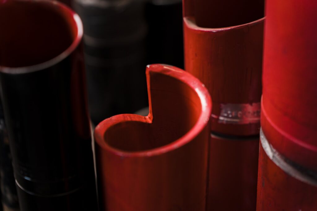
Spoolable Dimple Connector
Spoolable dimple connectors are critical in pipe recovery operations as an emergency splice between two lengths of coiled tubing. The central part of the connector has a smooth thru-bore and notched exterior profile. The notches allow a plastic bending modulus equal to the coiled tubing while preserving the OD so that the connector can be passed through the injector chains and the stuffing box.
Design Features
- Robust one-piece design
- High torsional & tensile strength
- Simple to install
- Dual elastomeric seals
- Available for all sizes of coiled tubing
- Customization options available
Technical Specifications
Engineered as an emergency splice solution, each configuration maintains CT bending modulus while preserving the original OD. The notched profile allows the connector to pass through injector chains and stuffing boxes during pipe recovery, maintaining full flow capacity and pressure integrity when CT failure means losing time downhole.
| COIL OD | WALL THICKNESS | STANDARD ID | FLOW AREA (sq. in.) | O-RING | TENSILE YIELD | TORSIONAL YIELD ft-lbs | INTERNAL YIELD PRESSURE |
| 60.3mm 2.375″ | 3.68mm 0.145″ | 38.1mm 1.500″ | 1.767 | 225 | 33,299 daN 74,590 lbf | 2,761 | 68.9 MPa 10,000 PSI |
| 60.3mm 2.375″ | 3.96mm 0.156″ | 38.1mm 1.500″ | 1.767 | 224 | 36,240 daN 81,179 lbf | 3,023 | 57.2 MPa 8,300 PSI |
| 60.3mm 2.375″ | 4.45mm 0.175″ | 36.5mm 1.438″ | 1.624 | 224 | 40,521 daN 90,769 lbf | 3,261 | 68.3 MPa 9,900 PSI |
| 60.3mm 2.375″ | 4.76mm 0.188″ | 34.8mm 1.370″ | 1.474 | 224 | 42,064 daN 94,224 lbf | 3,261 | 68.9 MPa 10,000 PSI |
| 60.3mm 2.375″ | 5.16mm 0.203″ | 33.3mm 1.312″ | 1.352 | 226 | 44,857 daN 100,480 lbf | 3,556 | 68.9 MPa 10,000 PSI |
Real Results Delivered.
CTC Permian Success.
Every well where the Universal Jet Thruster (UJT) was incorporated into the milling BHA was faster completing the plug milling than BHAs without it. Fastest long, lateral mill out time EVER for Top American Producer had the UJT in the Milling BHA!
Avg ft / min: 7.4
CTC Permian Success.
Lorem ipsum dolor sit amet, consectetur adipiscing elit. Pellentesque sit amet pharetra sem. Morbi gravida sapien luctus risus mollis mattis. Sed justo dui, feugiat nec ornare et, viverra et purus. Vestibulum tincidunt convallis nibh, in viverra tortor euismod ac. Suspendisse eu lobortis ipsum, at convallis urna.
Avg ft / min: 7.4
CTC Permian Success.
Phasellus mollis egestas metus sed semper. Sed non libero elit. Curabitur ornare viverra libero, sit amet elementum risus accumsan id. Vivamus congue bibendum vehicula. Etiam non semper sem. Donec vel vestibulum leo. Mauris sit amet ornare augue, in sollicitudin nibh.
Avg ft / min: 7.4
CTC Permian Success.
Lorem ipsum dolor sit amet, consectetur adipiscing elit. Pellentesque sit amet pharetra sem. Morbi gravida sapien luctus risus mollis mattis. Sed justo dui, feugiat nec ornare et, viverra et purus. Vestibulum tincidunt convallis nibh, in viverra tortor euismod ac. Suspendisse eu lobortis ipsum, at convallis urna.
Avg ft / min: 7.4